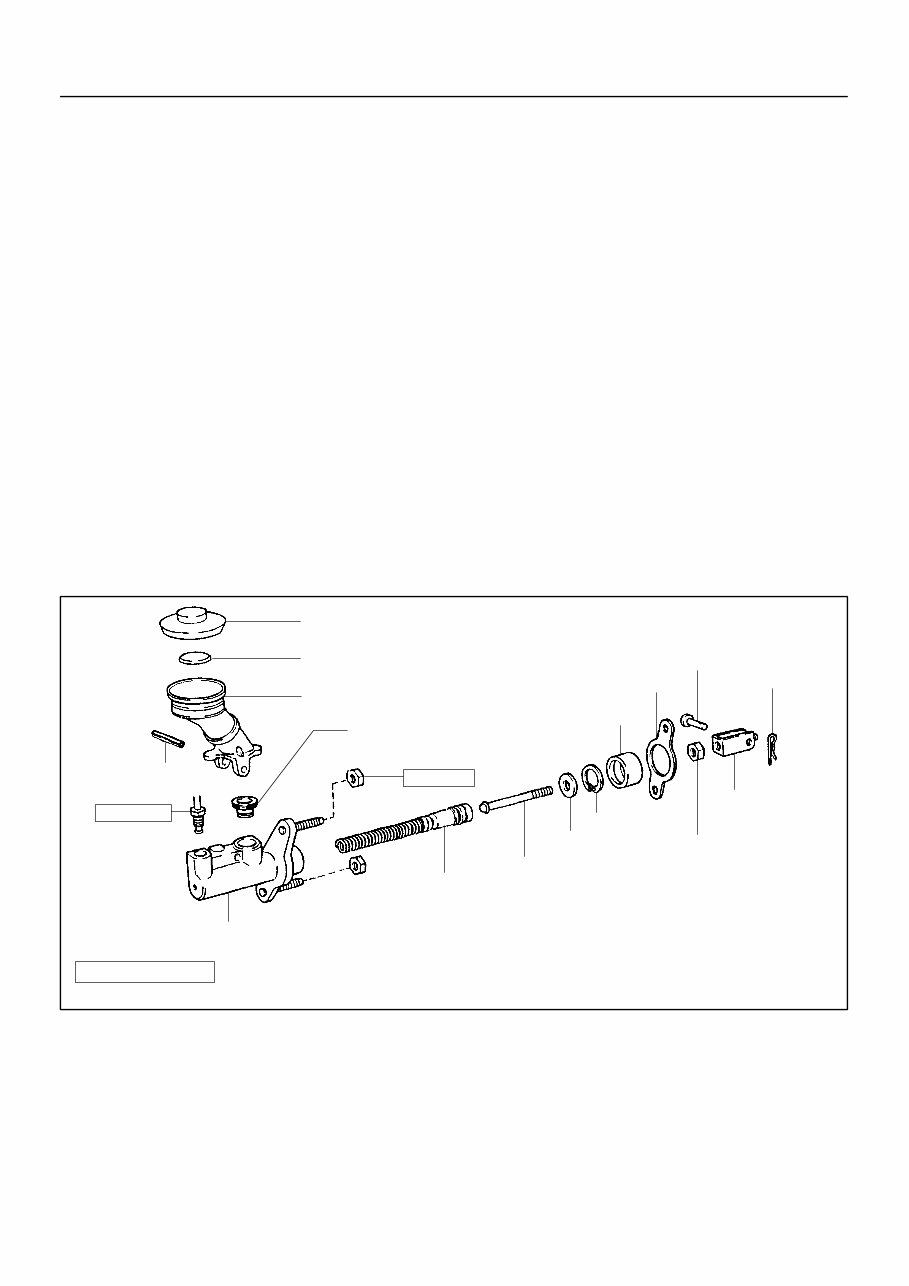
IN00U–36 N17080 Filler Cap Float Reservoir A Grommet Clip Slotted Spring Pin : Specified torque A Non–reusable part Cylinder Piston Push Rod Washer Snap Ring Boot A Gasket Lock Nut Clevis Pin Clevis N·m (kgf·cm, ft·lbf) 12 (120, 9) 15 (155, 11) – INTRODUCTION HOW TO USE THIS MANUAL IN–1 1 AuthorĂ: DateĂ: 2003 TOYOTA TUNDRA (RM956U) HOW TO USE THIS MANUAL GENERAL INFORMATION 1. INDEX An INDEX is provided on the first page of each section to guide you to the item to be repaired. To assist you in finding your way through the manual, the section title and major heading are given at the top of every page. 2. PRECAUTION At the beginning of each section, a PRECAUTION is given that pertains to all repair operations contained in that section. Read these precautions before starting any repair task. 3. TROUBLESHOOTING TROUBLESHOOTING tables are included for each system to help you diagnose the problem and find the cause. The fundamentals of how to proceed with troubleshooting are described on page IN–17. Be sure to read this before performing troubleshooting. 4. PREPARATION Preparation lists the SST (Special Service Tools), recommended tools, equipment, lubricant and SSM (Spe- cial Service Materials) which should be prepared before beginning the operation and explains the purpose of each one. 5. REPAIR PROCEDURES Most repair operations begin with an overview illustration. It identifies the components and shows how the parts fit together. Example:
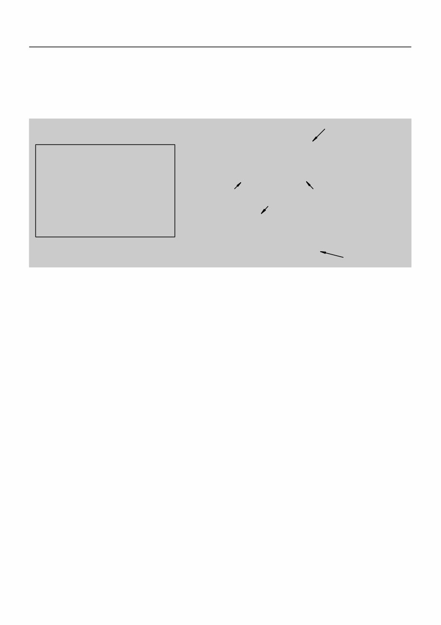
Illustration: what to do and where 21. CHECK PISTON STROKE OF OVERDRIVE BRAKE (a) Task heading : what to do SST 09350–30020 (09350–06120) Set part No. Component part No. Detailed text : how to do task (b) Piston stroke: 1.40 Ċ 1.70 mm (0.0551 Ċ 0.0669 in.) Specification Place SST and a dial indicator onto the overdrive brake pis- ton as shown in the illustration. Measure the stroke applying and releasing the compressed air (392 Ċ 785 kPa, 4 Ċ 8 kgf/cm 2 or 57 Ċ 114 psi) as shown in the illustration. IN–2 – INTRODUCTION HOW TO USE THIS MANUAL 2 AuthorĂ: DateĂ: 2003 TOYOTA TUNDRA (RM956U) The procedures are presented in a step–by–step format: Y The illustration shows what to do and where to do it. Y The task heading tells what to do. Y The detailed text tells how to perform the task and gives other information such as specifications and warnings. Example: This format provides the experienced technician with a FAST TRACK to the information needed. The upper case task heading can be read at a glance when necessary, and the text below it provides detailed informa- tion. Important specifications and warnings always stand out in bold type. 6. REFERENCES References have been kept to a minimum. However, when they are required you are given the page to refer to. 7. SPECIFICATIONS Specifications are presented in bold type throughout the text where needed. You never have to leave the procedure to look up your specifications. They are also found in Service Specifications section for quick ref- erence. 8. CAUTIONS, NOTICES, HINTS: Y CAUTIONS are presented in bold type, and indicate there is a possibility of injury to you or other people. Y NOTICES are also presented in bold type, and indicate the possibility of damage to the components being repaired. Y HINTS are separated from the text but do not appear in bold. They provide additional information to help you perform the repair efficiently. 9. SI UNIT The UNITS given in this manual are primarily expressed according to the SI UNIT (International System of Unit), and alternately expressed in the metric system and in the English System. Example: Torque: 30 N·m (310 kgf·cm, 22 ft·lbf)
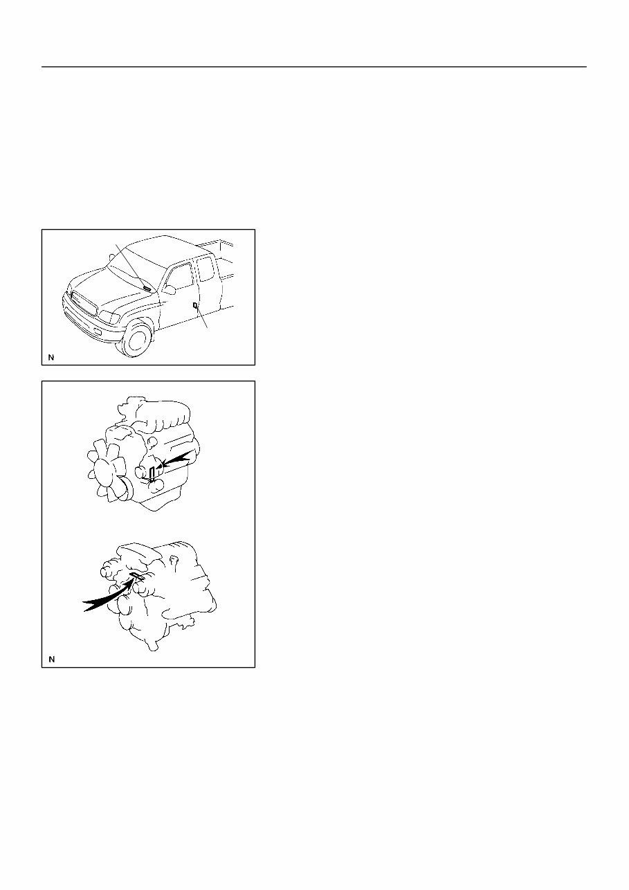
IN01P–04 B02417 A B B02418 5VZ–FE Engine 2UZ–FE Engine – INTRODUCTION IDENTIFICATION INFORMATION IN–3 3 AuthorĂ: DateĂ: 2003 TOYOTA TUNDRA (RM956U) IDENTIFICATION INFORMATION VEHICLE IDENTIFICATION AND ENGINE SERIAL NUMBER 1. VEHICLE IDENTIFICATION NUMBER The vehicle identification number is stamped on the vehicle identification number plate and certification label. A: Vehicle Identification Number Plate B: Certification Label 2. ENGINE SERIAL NUMBER The engine serial number is stamped on the engine block, as shown in the illustration.
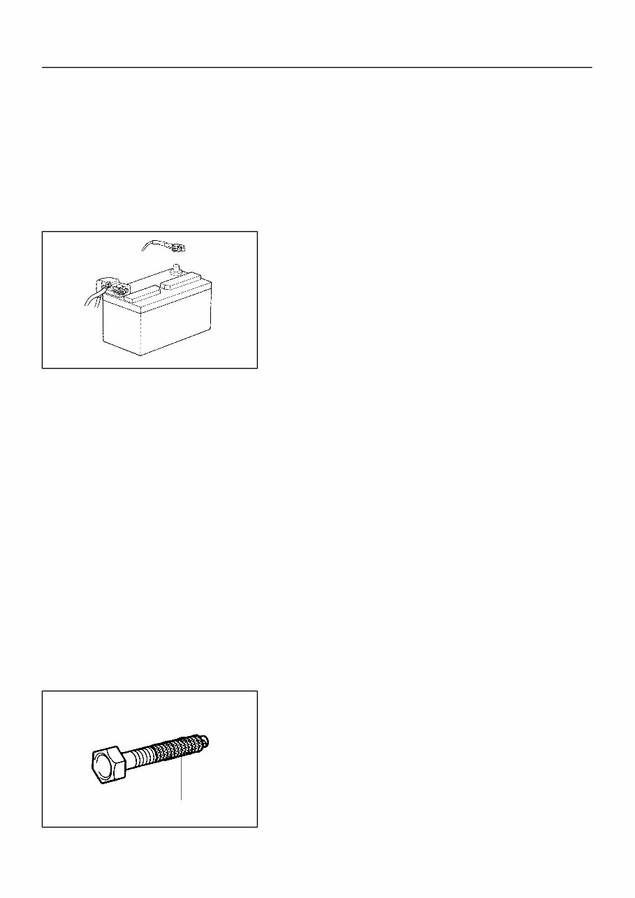
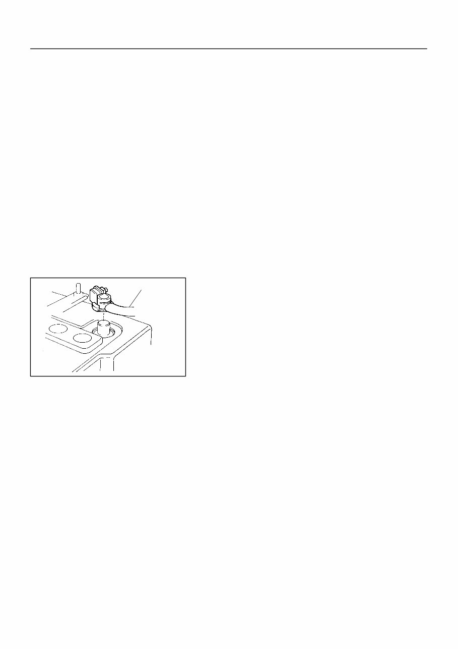
IN0CO–12 FI1066 Z11554 Seal Lock Adhesive IN–4 – INTRODUCTION REPAIR INSTRUCTIONS 4 AuthorĂ: DateĂ: 2003 TOYOTA TUNDRA (RM956U) REPAIR INSTRUCTIONS GENERAL INFORMATION BASIC REPAIR HINT (a) Use fender, seat and floor covers to keep the vehicle clean and prevent damage. (b) During disassembly, keep parts in the appropriate order to facilitate reassembly. (c) Installation and removal of battery terminal: (1) Before performing electrical work, disconnect the negative (–) terminal cable from the battery. (2) If it is necessary to disconnect the battery for in- spection or repair, first disconnect the negative (–) terminal cable. (3) When disconnecting the terminal cable, to prevent damage to battery terminal, loosen the cable nut and raise the cable straight up without twisting or prying it. (4) Clean the battery terminals and cable ends with a clean shop rag. Do not scrape them with a file or oth- er abrasive objects. (5) Install the cable ends to the battery terminals after loosening the nut, and tighten the nut after installa- tion. Do not use a hammer to tap the cable ends onto the terminals. (6) Be sure the cover for the positive (+) terminal is properly in place. (d) Check hose and wiring connectors to make sure that they are connected securely and correctly. (e) Non–reusable parts (1) Always replace cotter pins, gaskets, O–rings, oil seals, etc. with new ones. (2) Non–reusable parts are indicated in the component illustrations by the ” ” symbol. (f) Precoated parts Precoated parts are bolts, nuts, etc. that are coated with a seal lock adhesive at the factory. (1) If a precoated part is retightened, loosened or caused to move in any way, it must be recoated with the specified adhesive. (2) When reusing precoated parts, clean off the old adhesive and dry with compressed air. Then apply the specified seal lock adhesive to the bolt, nut or threads.
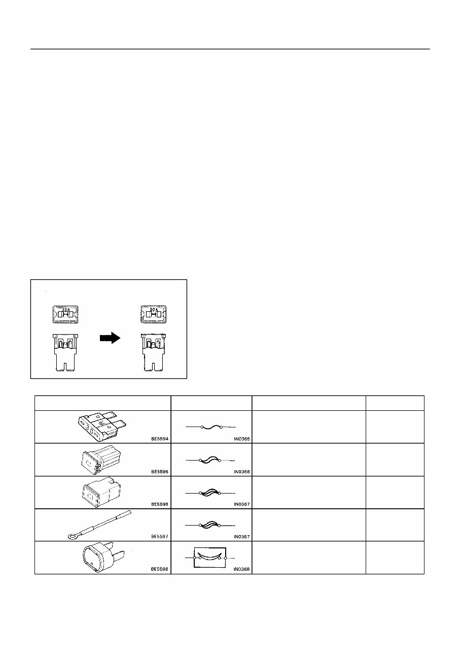
BE1367 Medium Current Fuse and High Current Fuse Equal Amperage Rating V00076 Abbreviation Part Name Symbol Illustration FUSE MEDIUM CURRENT FUSE HIGH CURRENT FUSE FUSIBLE LINK CIRCUIT BREAKER FUSE M–FUSE H–FUSE FL CB – INTRODUCTION REPAIR INSTRUCTIONS IN–5 5 AuthorĂ: DateĂ: 2003 TOYOTA TUNDRA (RM956U) (3) Precoated parts are indicated in the component il- lustrations by the ”Y” symbol. (g) When necessary, use a sealer on gaskets to prevent leaks. (h) Carefully observe all specifications for bolt tightening torques. Always use a torque wrench. (i) Use of special service tools (SST) and special service ma- terials (SSM) may be required, depending on the nature of the repair. Be sure to use SST and SSM where speci- fied and follow the proper work procedure. A list of SST and SSM can be found in Preparation section in this manual. (j) When replacing fuses, be sure the new fuse has the cor- rect amperage rating. DO NOT exceed the rating or use one with a lower rating.
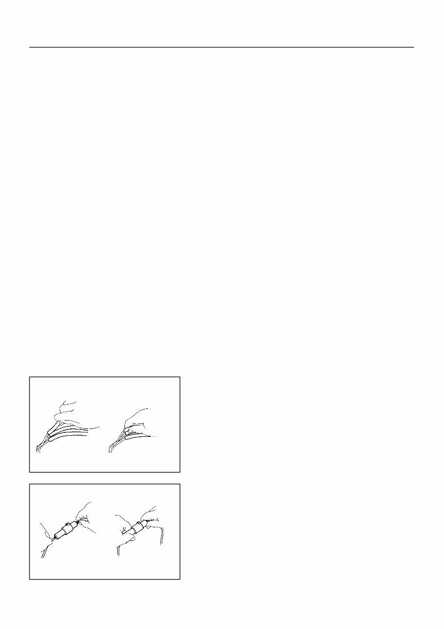
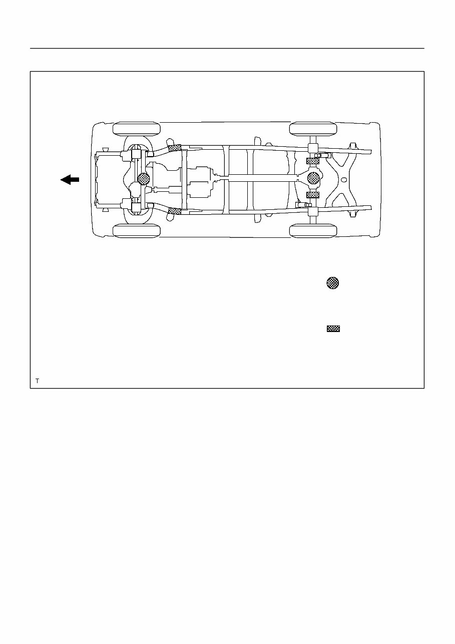
IN0253 WRONG CORRECT IN0252 WRONG CORRECT IN–6 – INTRODUCTION REPAIR INSTRUCTIONS 6 AuthorĂ: DateĂ: 2003 TOYOTA TUNDRA (RM956U) (k) Care must be taken when jacking up and supporting the vehicle. Be sure to lift and support the vehicle at the prop- er locations (See page IN–8). A Cancel the parking brake on the level place and shift the transmission in Neutral (or N position). A When jacking up the front wheels of the vehicle at first place stoppers behind the rear wheels. A When jacking up the rear wheels of the vehicle at first place stoppers before the front wheels. A When either the front or rear wheels only should be jacked up, set rigid racks and place stoppers in front and behind the other wheels on the ground. A After the vehicle is jacked up, be sure to support it on rigid racks . It is extremely dangerous to do any work on a vehicle raised on a jack alone, even for a small job that can be finished quickly. (l) Observe the following precautions to avoid damage to the following parts: (1) Do not open the cover or case of the ECU unless absolutely necessary. (If the IC terminals are touched, the IC may be destroyed by static electric- ity.) (2) To disconnect vacuum hoses, pull off the end, not the middle of the hose. (3) To pull apart electrical connectors, pull on the con- nector itself, not the wires. (4) Be careful not to drop electrical components, such as sensors or relays. If they are dropped on a hard floor, they should be replaced and not reused. (5) When steam cleaning an engine, protect the elec- tronic components, air filter and emission–related components from water. (6) Never use an impact wrench to remove or install temperature switches or temperature sensors.
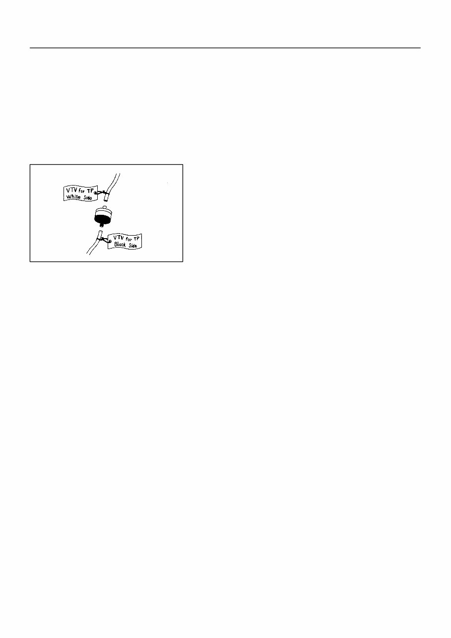
IN0002 Example – INTRODUCTION REPAIR INSTRUCTIONS IN–7 7 AuthorĂ: DateĂ: 2003 TOYOTA TUNDRA (RM956U) (7) When checking continuity at the wire connector, in- sert the tester probe carefully to prevent terminals from bending. (8) When using a vacuum gauge, never force the hose onto a connector that is too large. Use a step–down adapter for adjustment. Once the hose has been stretched, it may leak air. (m) Installation and removal of vacuum hose: (1) When disconnecting vacuum hoses, use tags to identify how they should be reconnected to. (2) After completing a job, double check that the vacu- um hoses are properly connected. A label under the hood shows the proper layout. (n) Unless otherwise stated, all resistance is measured at an ambient temperature of 20°C (68°F). Because the resis- tance may be outside specifications if measured at high temperatures immediately after the vehicle has been run- ning, measurement should be made when the engine has cooled down.
IN0DY–01 B07972 JACK POSITION A A A A A A A A A A A A A A A A A A Front A A A A A A A A A Center of crossmember Rear A A A A A A A A A Center of rear axle housing SUPPORT POSITION Safety stand A A A A A A A A A A A A A A A A Front IN–8 – INTRODUCTION REPAIR INSTRUCTIONS 8 AuthorĂ: DateĂ: 2003 TOYOTA TUNDRA (RM956U) VEHICLE LIFT AND SUPPORT LOCATIONS
IN0DB–04 BO4111 Negative Cable – INTRODUCTION FOR ALL OF VEHICLES IN–9 9 AuthorĂ: DateĂ: 2003 TOYOTA TUNDRA (RM956U) FOR ALL OF VEHICLES PRECAUTION 1. FOR VEHICLES EQUIPPED WITH SRS AIRBAG AND SEAT BELT PRETENSIONER (a) The TOYOTA TUNDRA is equipped with an SRS (Sup- plemental Restraint System), such as the driver airbag, front passenger airbag assembly and seat belt preten- sioner. Failure to carry out service operations in the correct se- quence could cause the supplemental restraint system to unexpectedly deploy during servicing, possibly leading to a serious accident. Further, if a mistake is made in servicing the supplemental restraint system, it is possible the SRS may fail to operate when required. Before servicing (including removal or installation of parts, inspection or replacement), be sure to read the following items carefully, then follow the cor- rect procedure described in this manual. (b) GENERAL NOTICE (1) Malfunction symptoms of the supplemental re- straint system are difficult to confirm, so the diag- nostic trouble codes become the most important source of information when troubleshooting. When troubleshooting the supplemental restraint system, always inspect the diagnostic trouble codes before disconnecting the battery (See page DI–490). (2) Work must be started after 90 seconds from the time the ignition switch is turned to the ”LOCK” posi- tion and the negative (–) terminal cable is discon- nected from the battery. (The supplemental restraint system is equipped with a back–up power source so that if work is started within 90 seconds of disconnecting the neg- ative (–) terminal cable from the battery, the SRS may deploy.) When the negative (–) terminal cable is discon- nected from the battery, memory of the clock and audio systems will be cancelled. So before starting work, make a record of the contents memorized by the each memory system. Then when work is fin- ished, reset the clock and audio systems as before. To avoid erasing the memory of each memory sys- tem, never use a back–up power supply from anoth- er battery.
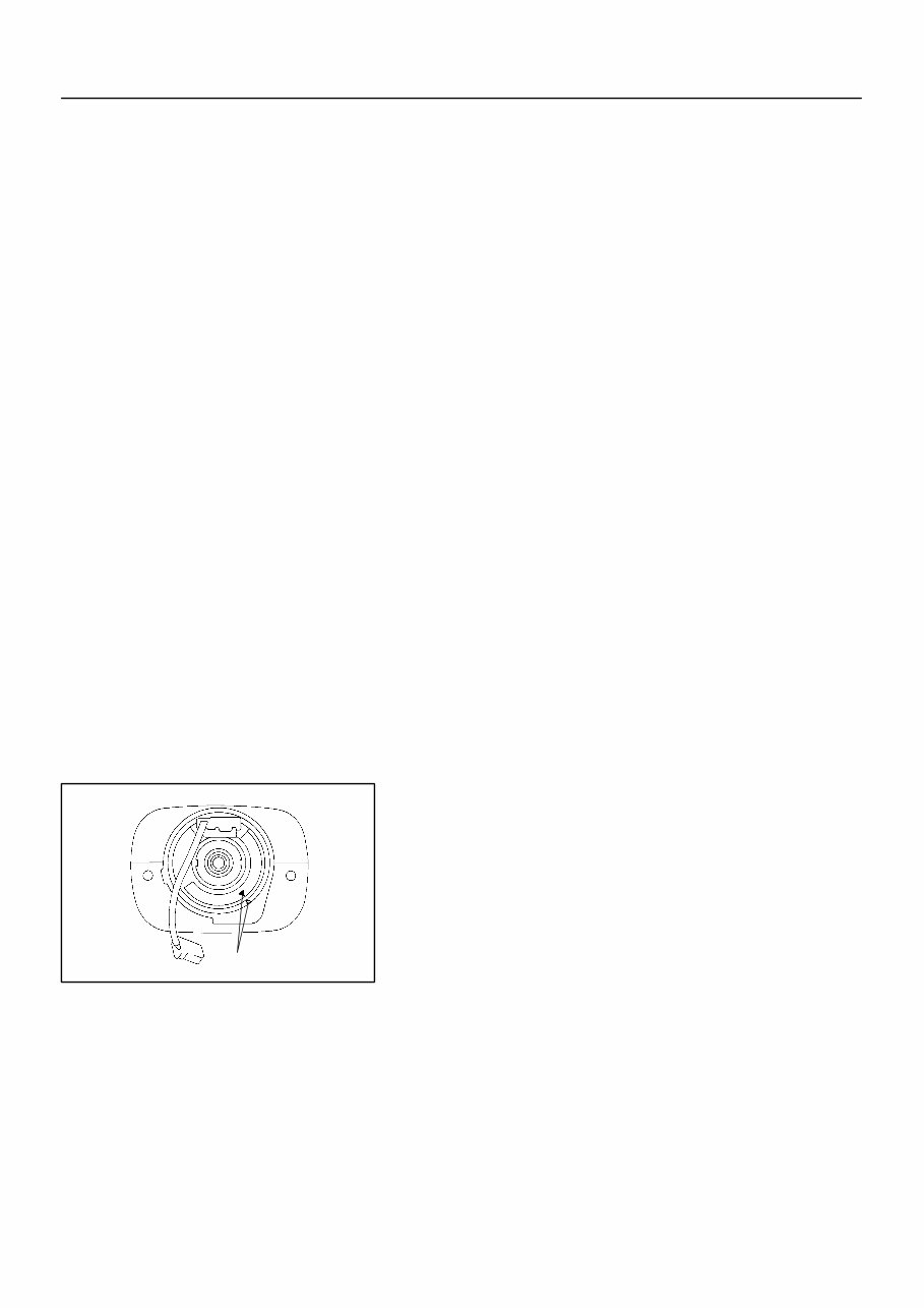
F04784 Mark IN–10 – INTRODUCTION FOR ALL OF VEHICLES 10 AuthorĂ: DateĂ: 2003 TOYOTA TUNDRA (RM956U) (3) Even in cases of a minor collision where the SRS does not deploy, the steering wheel pad (See page RS–12), front passenger airbag assembly (See page RS–26) and seat belt pretensioner (See page BO–140 ) should be inspected. (4) Never use SRS parts from another vehicle. When replacing parts, replace them with new parts. (5) Before repairs, remove the airbag sensor if shocks are likely to be applied to the sensor during repairs. (6) Never disassemble and repair the airbag sensor as- sembly, steering wheel pad, front passenger airbag assembly or seat belt pretensioner. (7) If the airbag sensor assembly, steering wheel pad, front passenger airbag assembly or seat belt pre- tensioner has been dropped, or if there are cracks, dents or other defects in the case, bracket or con- nector, replace them with new ones. (8) Do not directly expose the airbag sensor assembly, steering wheel pad, front passenger airbag assem- bly or seat belt pretensioner to hot air or flames. (9) Use a volt/ohmmeter with high impedance (10 kΩ/V minimum) for troubleshooting of the electrical cir- cuit. (10) Information labels are attached to the periphery of the SRS components. Follow the instructions on the notices. (11) After work on the supplemental restraint system is completed, check the SRS warning light (See page DI–490). (c) SPIRAL CABLE (in Combination Switch) The steering wheel must be fitted correctly to the steering column with the spiral cable at the neutral position, other- wise cable disconnection and other troubles may result. Refer to SR–28 concerning correct steering wheel instal- lation.
You're Reading a Preview
What's Included?
Lifetime Access
Fast Download Speeds
Online & Offline Access
Access PDF Contents & Bookmarks
Full Search Facility
Print one or all pages of your manual
$36.99
2001 Toyota Tundra Service & Repair Manual Software
Introducing the 2001 Toyota Tundra Service & Repair Manual. This comprehensive manual is specifically designed to assist you in maintaining, servicing, and repairing your 2001 Toyota Tundra with ease and accuracy. It is useful for both professional mechanics and DIY enthusiasts.
Equipped with detailed instructions and diagrams, this manual provides step-by-step guidance for various repair procedures, ensuring that you can tackle any issue that may arise. Whether it's routine maintenance tasks or more complex repairs, this manual has got you covered.
Some of the highlights of this Service & Repair Manual include:
Comprehensive coverage of all aspects of the 2001 Toyota Tundra
Detailed instructions for maintenance procedures
Step-by-step guidance for various repairs
Illustrations and diagrams to aid in understanding
Easy-to-use interface for seamless navigation
With the 2001 Toyota Tundra Service & Repair Manual, you have everything you need to keep your vehicle running smoothly. Say goodbye to costly visits to the mechanic and take control of your own vehicle maintenance.
Invest in this manual today and empower yourself with the knowledge and tools to take care of your 2001 Toyota Tundra.
Reviews
Q&A
Recently Viewed
5,521,897Happy Clients
2,594,462eManuals
1,120,453Trusted Sellers
15Years in Business
Price:
Actual Price:
2001 Toyota Tundra Service & Repair Manual Software
Top Quality Store on Shopper Approved
eManualOnline has earned over 64,000+ 5 star reviews while providing its customers an excellent shopping experience.


 Lifetime Access




